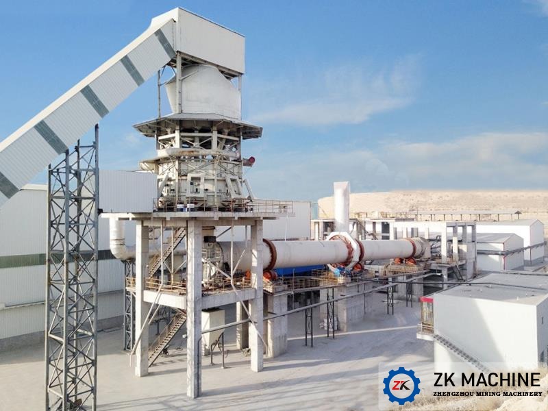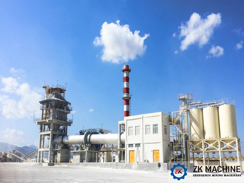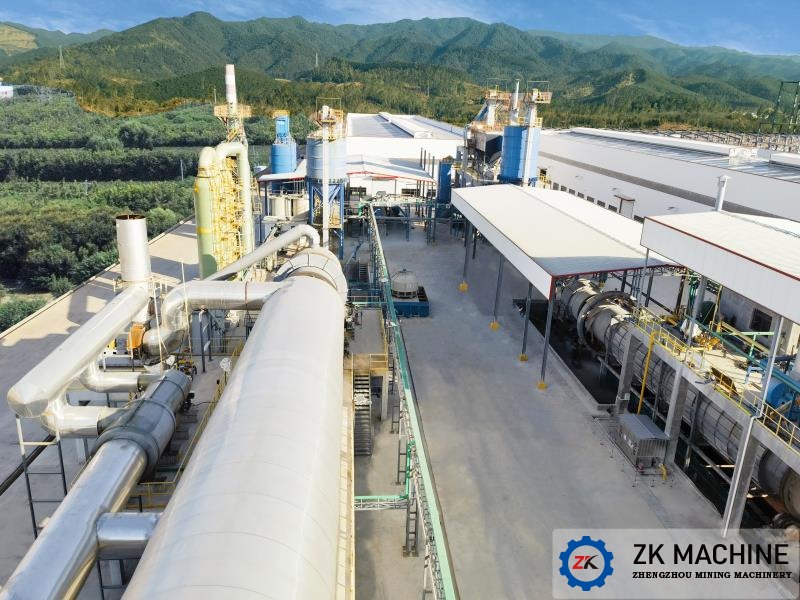
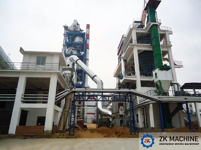
Guangdong 100,000 m³/a Ceramsite Production Line Project
100,000 m³/a
Guangdong
Signed Date: August 28, 2018
Processed Materials: Sand and waste soil, etc.
Processing Capacity: 100,000 cm³/a
Equipment: One plug-in rotary kiln, one cooler, one double-roller granulator, and two twin-shaft mixers
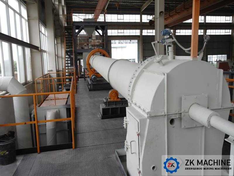
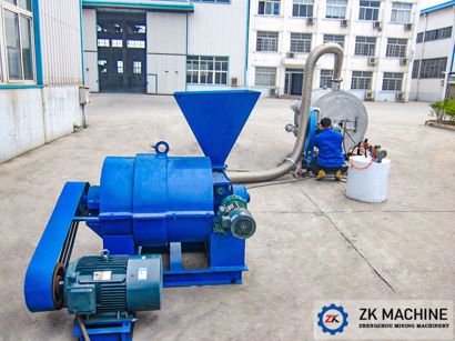
1. Loading System
After a period of storage, washed sand waste is transported by a loader to a box feeder. The box feeder evenly feeds the weighing scale, which then conveys the washed sand waste to a twin-shaft mixer at a specified delivery rate. The primary twin-shaft mixer pre-mixes the raw materials, then continues mixing in the secondary mixer. The mixed material flows through a chute into a double-roller granulator for granulation. The raw material pellets are then shaped in a shaping machine. After the broken raw material pellets are screened out, the qualified ceramsite enters a rotary kiln for calcination.
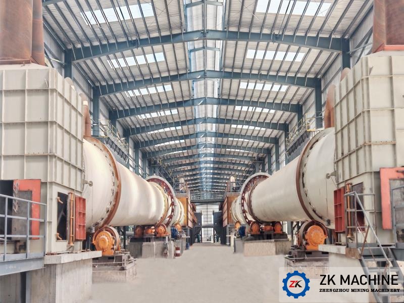
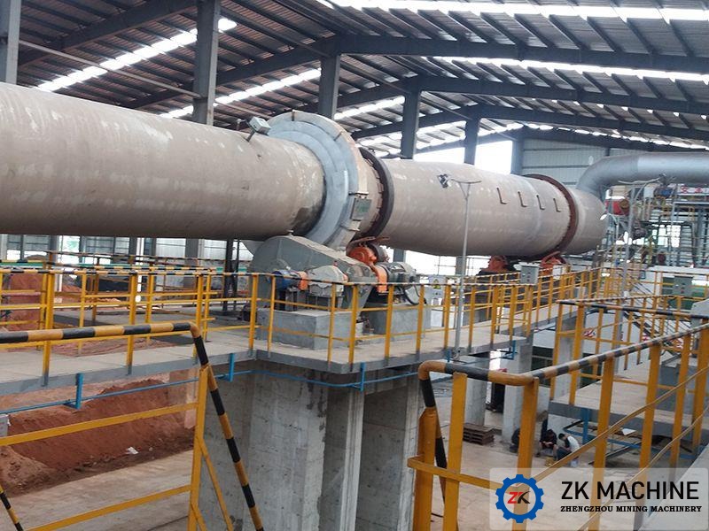
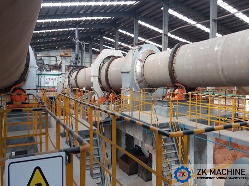
2. Firing System
The ceramsite first enters a double-flap valve at the kiln outlet. The valve's gravity-enforced action seals the kiln exhaust, preventing it from escaping. Through the kiln outlet chute, the ceramsite enters a drying kiln for drying. As it slowly advances through the rotary kiln into the calcining kiln, the temperature of the ceramsite gradually increases, and its moisture evaporates. When the ceramsite enters the calcining kiln, it is rapidly heated, reacting and calcining into ceramic particles. The calcined ceramsite flows out of the rotary kiln head and passes through a single-drum cooler for cooling. The cooled ceramsite is then lifted by a bucket elevator to a rotary screen for screening. After screening by a drum screen, the ceramsite is sorted into different particle sizes and stored in a stockpile for packaging and export.
Procured biomass fuel is transported by truck to the biomass fuel storage workshop. After manual unpacking and loading, the biomass fuel is lifted by a bucket elevator and stored in the biomass fuel silo. A screw feeder at the bottom of the biomass fuel silo delivers the biomass fuel to the burner pipe, where it is blown into the rotary kiln by the combustion fan for combustion. 3. Exhaust Gas Treatment System
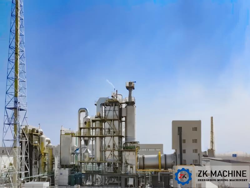
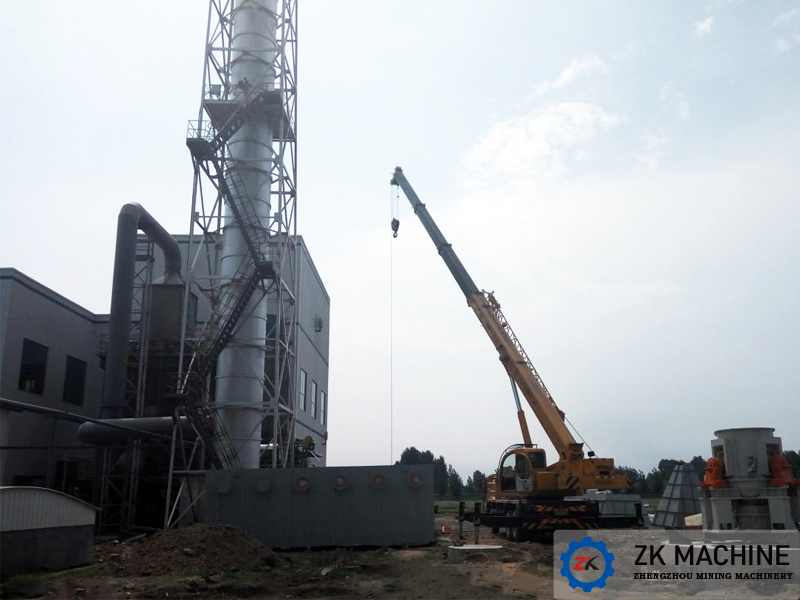
The hot flue gas from the kiln exhaust first passes through the kiln exhaust chamber for dust removal. It then enters a cyclone dust collector for dust removal and cooling. The cooled flue gas then enters a bag filter for further dust removal. The flue gas, which meets the dust concentration standard of ≤30mg/m³, is then discharged through a steel chimney by the kiln exhaust fan.

Indonesia pulverized coal combustion system
Hanzhong Zinc Pulverized Coal Preparation System
Heze Yuncheng Shengda Ruyi Pulverized Coal Preparation Station
200,000 t/a Pulverized Coal Preparation Station of Shandong Dongjia Group
Southest Asia 60 tph Cement Grinding Project
150 T/D Lime Project in Uzbekistan
Contact Us
Send message & get quote